Smart Plumbing with Sensors and Metrics
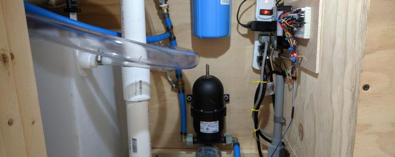
Currently, there are several temperature and humidity sensors throughout the tiny house. One resides underneath the sink with the majority of the plumbing. Now, it’s time to take that IoT device to the next level and add more sensors to create a smart plumbing system.
In addition to temperature and humidity tracking, the smart plumbing system includes sensors to measure water flow, water depth, and water detection. These sensors will all work together on a single Raspberry Pi 3 running custom software to collect the data and send alerts.
Why Build a Smart Plumbing System
A typical house has plumbing that supplies water throughout the house and removes waste water. Plumbing is likely one of the most important systems that needs to be in working order at all times. Yet, we don’t think about plumbing when everything is running fine.
The purpose of the smart plumbing system is awareness. The system will answer questions such as: Is there any water leaks or freezing temperatures? How much water has been used? Is the water tank almost empty? And more. These are practical uses for a smart plumbing system. The other reason is that it’s very cool.
The Smart Plumbing System Parts List
The following electronic components are part of the smart plumbing system:
- Raspberry Pi 3 B+ ($35)
- Smraza Ultimate Starter Kit for Raspberry Pi 3 B+ ($30)
- AM2302 (wired DHT22) temperature-humidity sensor ($15)
- Liquid Flow Meter – Plastic 1/2″ NPS Threaded ($10)
- Kuman 5PCS Soil Moisture Sensor Kit ($9)
- MCP3008 – 8-Channel 10-Bit ADC With SPI Interface ($4)
- Standard eTape® assembly ($60)
- one 10K ohm resistor ($7 for 100)
These adapters are specific to the PEX system in the tiny house:
- (2x) NPT 1/2″ male to NPS 1/2″ female adapters ($55 each)
- (2x) PEX to 1/2″ FNPT female adapters ($20 for 5 pack)
Note: The prices reflect what they were at the time of this writing.
The Temperature Sensor
The purpose of the temperature and humidity sensor is to track the temperature so it does not fall below freezing. Although this is highly unlikely, it still is possible if, for example, the HVAC fails during the winter.
The temperature sensor already is part of the smart plumbing device. However, other sensors require 5V. Therefore, I moved the power pin from PIN 2 (5V) to PIN 1 (3.3V). This is possible since the specifications of the AM2302 Sensor operates between 3.3V – 5.5V. Thankfully, everything still works as it did before. I confirmed this by manually running the software that collects the temperature and humidity metrics.
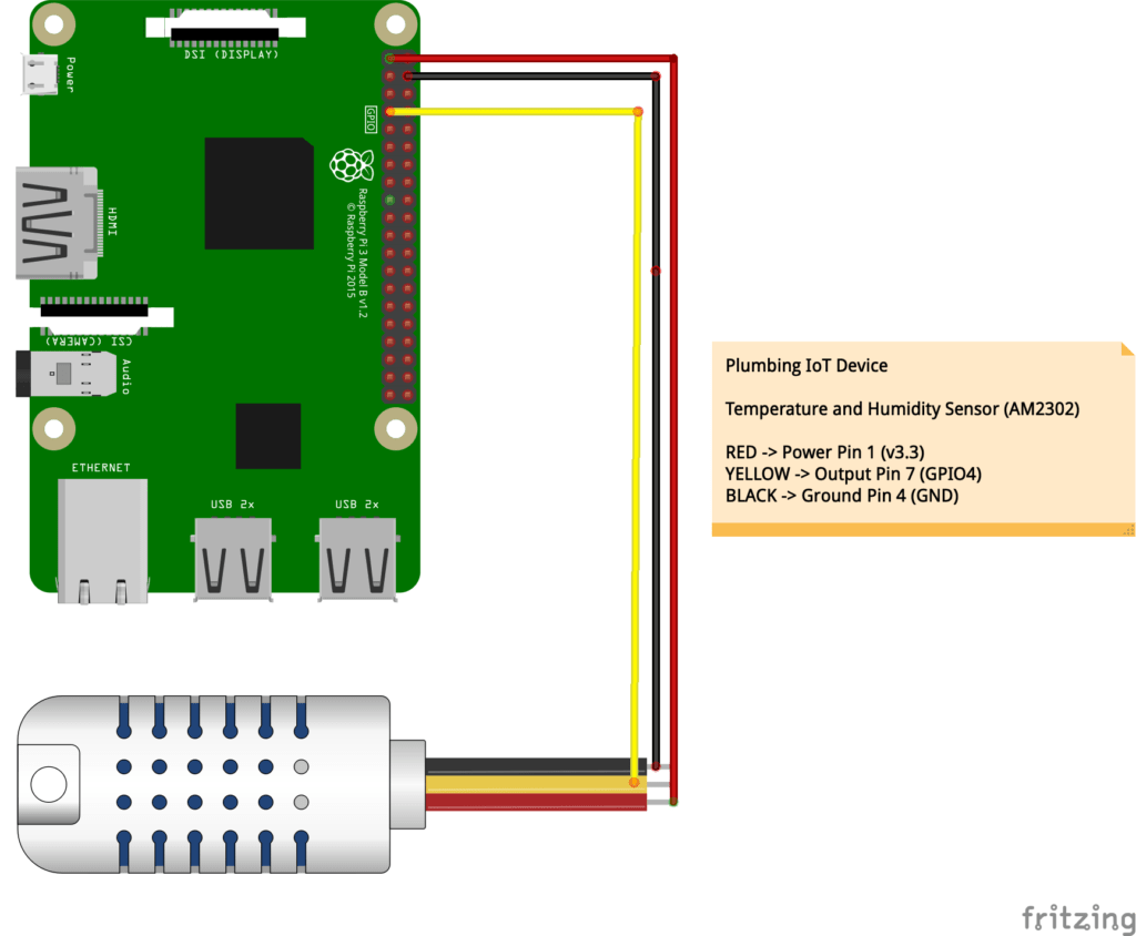
A standalone temperature sensor requires a Raspberry Pi 3 or Raspberry Pi Zero W and an AM2302 Sensor. Scripts to read the data are available here.
Liquid Flow Meter Sensor
A liquid flow meter sensor measures water volume by counting the number of pulses from water flow. The specifications state that 450 pulses equals 1 liter. For my American friends, that’s approximately 1,703 pulses for 1 gallon.
Unlike the other sensors, the data from the sensor is the total number of pulses since the sensor was last started. However, I want to collect data on a per-minute basis. Therefore, the software must calculate the difference from the current value and the previous value to determine water flow over a period of time.
For example, the first minute has a value of 300 pulses. Therefore, 300 pulses or (300/450) 0.67 liters (~ 0.18 gallons) of water was used. After the second minute, the value is 2100. That means that during the second minute (2100 – 300) 1800 pulses or (1800/450) 4 liters (~ 1.06 gallons) of water was used. Thereby the total usage over the two minutes was 4.67 liters (~ 1.24 gallons).
By measuring the data in this manner, I can track water usage throughout the day instead of an overall value. This will identify water use over both short and long periods of time. Otherwise, the value will identify how many pulses happened since the smart plumbing system was started, which in my opinion isn’t very useful.
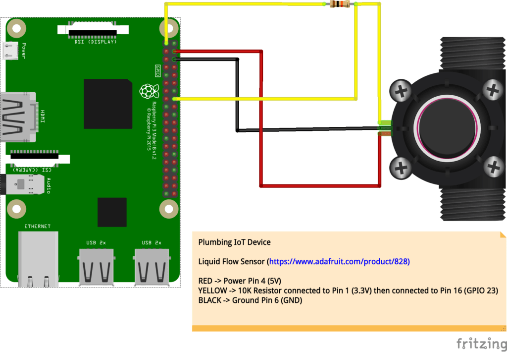
The flow sensor uses 5V from Pin 4 for power. The data wire connects to Pin 1 (3.3V) with a 10K resistor that connects to Pin 16 (GPIO 23). Lastly, the ground wire connects to Pin 6.
A standalone water flow sensor requires a Raspberry Pi 3 or Raspberry Pi Zero W and a Liquid Flow Meter Sensor. Scripts to read the data are available here.
Water Detection Sensor
Measuring data is great. However, it’s important to become aware of problems when they happen. A leak can be costly to repair. Therefore, a moisture sensor can detect leaks. When the sensor comes in contact with water, it sends a signal to the GPIO. Additionally, this sensor has an LED that visibly shows whether there is water. When water is present, the LED turns green. Otherwise, it is red.
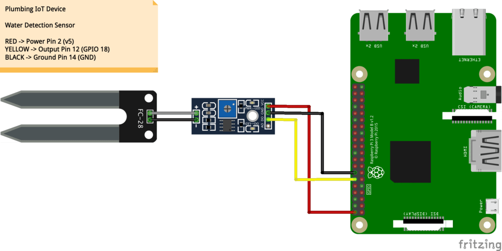
The water detection sensor uses 5V from Pin 2 for power. The data wire connects to Pin 12 (GPIO 18). Lastly, the ground wire connects to Pin 14.
When reading the sensor, the output is either true (there is water) or false (there is no water). However, I want to track the data over time to utilize it in different ways. Therefore, true will equal 100, and false will equal 0. Hopefully, this sensor never triggers an alarm, and the plumbing remains leak free.
A standalone water detection sensor requires a Raspberry Pi 3 or Raspberry Pi Zero W and a Kuman Soil Moisture Sensor. Scripts to read the data are available here.
eTape Water Level Sensor
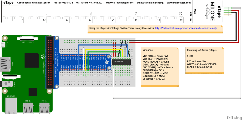
The eTape sensor will track how much water is in the 46 gallon (~ 174 liter) holding tank. This sensor is the most complicated part of the smart plumbing system. Unlike the other sensors, the eTape sensor requires a digital to analog conversion. In order to read analog data with a Raspberry Pi, an MCP3008 chip is necessary. This makes the smart plumbing system a little more complicated. However, for those who haven’t used an MCP3008 before, this tutorial is a good primer.
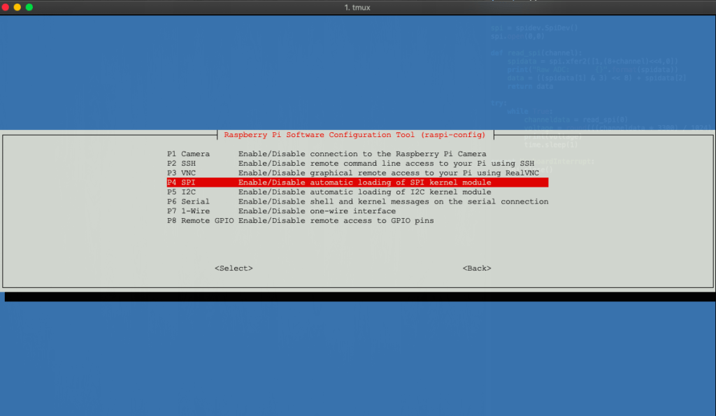
To use the Raspberry Pi with an MCP3008 chip, the I2C and SPI interfaces must be enabled. They are off by default. Use the raspi-config command to enable the I2C and SPI interfaces.
A standalone eTape water depth sensor setup requires a Raspberry Pi 3 or Raspberry Pi Zero W, an MCP3008 chip, and an eTape Sensor. Scripts to read the data are available here.
There are several tutorials and methods online that demonstrate how to set up an eTape sensor. However, I am using a slightly different approach that requires manually calibrating ranges to measure water depth.
Measuring Water Depth
The wiring is similar to the tutorial which demonstrates a dial that controls the volume of the Raspberry Pi. Therefore, this approach uses the raw ADC count from GPIO 22 to determine the current water depth.
The ADC value from the GPIO are numbers between 0 to 65535. Unfortunately, the results aren’t quite linear. Therefore, calculating the depth using the overall minimum value, the overall maximum value, and current value will be inaccurate.
Most of the tutorials require a calibration process to accurately (or very closely) measure water depth with an eTape. My method is to simply measure the ADC values for each inch of the eTape sensor. Then, use those values to calculate the water depth.
During this process, I made two observations. First, the eTape requires 5V. With 3.3V, the ADC values would stop increasing after 8 inches (~ 20 cm) since the ADC values exceed the 0 – 65535 range. Therefore, connecting the VDD and Vref pins on the MSP3008 chip to 5V resolved the issue. Secondly, the eTape doesn’t reliably measure between 0 and 1 inch.
Depth  Low ADC  High ADC
0      33088    33216
1      33217    33600
2      33601    34112
3      34113    35392
4      35393    36544
5      36545    37440
6      37441    38592
7      38593    39872
8      39873    40960
9      40961    42432
10     42433    43712
11     43713    45312
12     45313    46592
13     46953    47872
14     47873    49856
15     49857    51584
16     51583    53440
17     53441    55040
18     55041    56324
Once the ADC value ranges per inch are known, fractions of inches can be calculated. For example, a value of 44048 falls within the 11 inch range of 43713 and 45312. Next, the depth can be determined using the following formula:
Depth - (1 - ((value - low) / (high - low))))

11 - (1 - ((44048 - 43713) / (45312 - 43713))))
11 - (1 - (335 / 1599))
11 - (1 - 0.21)
11 - 0.79 = 10.21 inches
For my metric friends, multiply the depth in inches (10.21) by 2.54 to convert the depth into centimeters:
10.21 x 2.54 = 25.94 cm
Lastly, to calculate how full the tank is, divide the depth in inches (10.21) by the maximum depth of the eTape sensor in inches (18):
10.21 / 18 = 0.68 or 68%
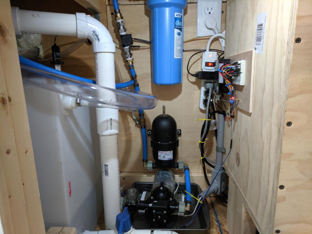
Installing the Smart Plumbing System
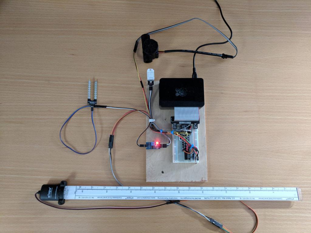
Now with all the sensors together, the smart plumbing system is ready to install inside the tiny house. Beyond the electronic sensors, there are a few plumbing components necessary.
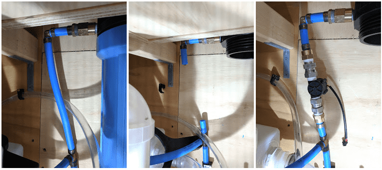
The liquid flow sensor is NPS (National Pipe Straight) threaded. Most PEX piping and adapters are NPT (National Pipe Taper) threaded. Therefore, I purchased two NPT 1/2″ male to NPS 1/2″ female adapters to connect with two PEX to 1/2″ FNPT female adapters.

The next sensor is the water detection sensor. All that is required is to place it within the water pan. If the pan fills with the smallest of puddles around the sensor, it triggers the alarm. Furthermore, the hose in the pan will help drain excess water into the drain pipes.

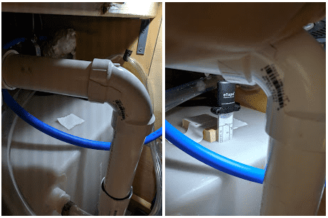
Lastly, the eTape water level sensor requires a small hole in the water reserve tank. The sensor is then slipped through the hole to the bottom of the tank. Although the sensor is 18″ (~ 46 cm) long, the tank is full at 15″ (~ 38 cm). Since the sensor is buoyant, there is a block of wood to keep it steady inside the tank.
Other than some minor cable management, the temperature and humidity sensor has not changed since the original installation.
Smart Plumbing in Action
Now that all the sensors are in place, it’s time to see some real action! First, I slowly opened the main valve to the pump so it could pump water into the plumbing. After a couple of moments, the pump stopped. This indicates the pipes are full of water, pressurized, and that there are no holes or air leaks in the pipes. Not only did I install the liquid flow meter correctly, the pipes survived another winter.
Next, I powered on the smart plumbing sensors and started the software that will gather the precious data. No errors! So far, so good. Now, let’s check the accuracy of the new sensors.
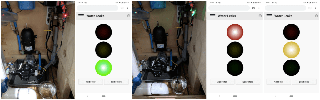
Water Detection Sensor Test
Using a cup with water and my smartphone, I can confirm everything is in working order. There are three LED indicators for this sensor. The obvious ones are RED (active leak) and GREEN (no leak). However, I want an indication that a leak has occurred but not at the moment. That special state is yellow.
There will be more work around this sensor relating to the software where alerts from the various sensors in the tiny house interact through texts, the MagicMirror, and voice notifications. However, that’s a topic for another time.
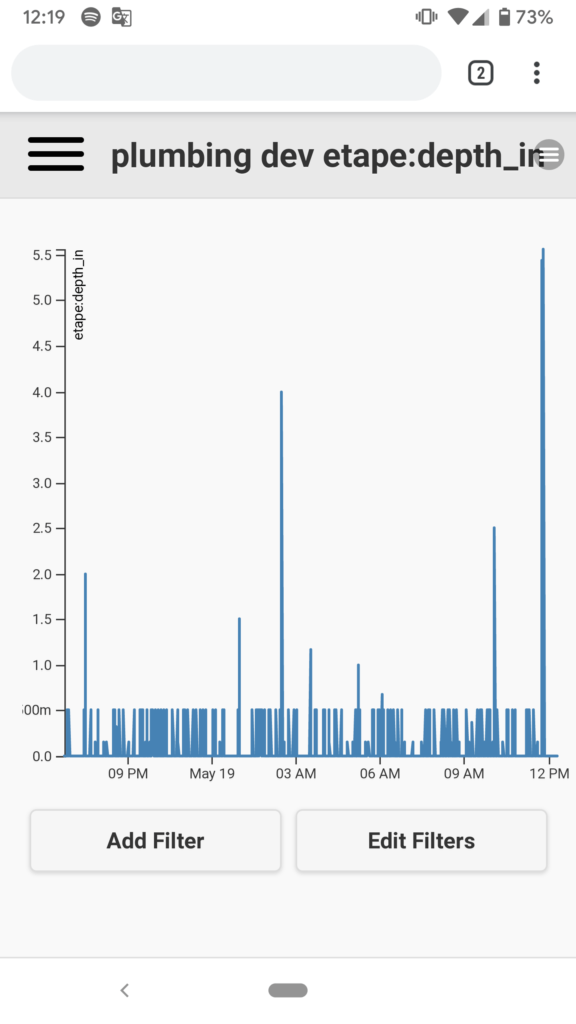
Water Depth Sensor Test
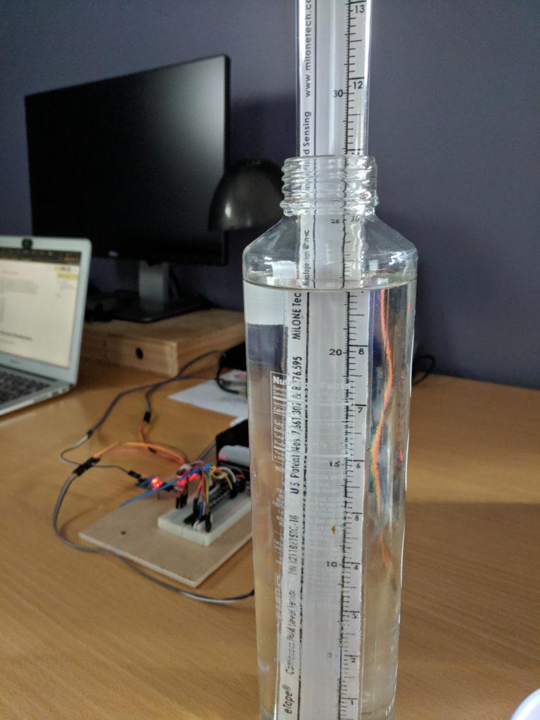
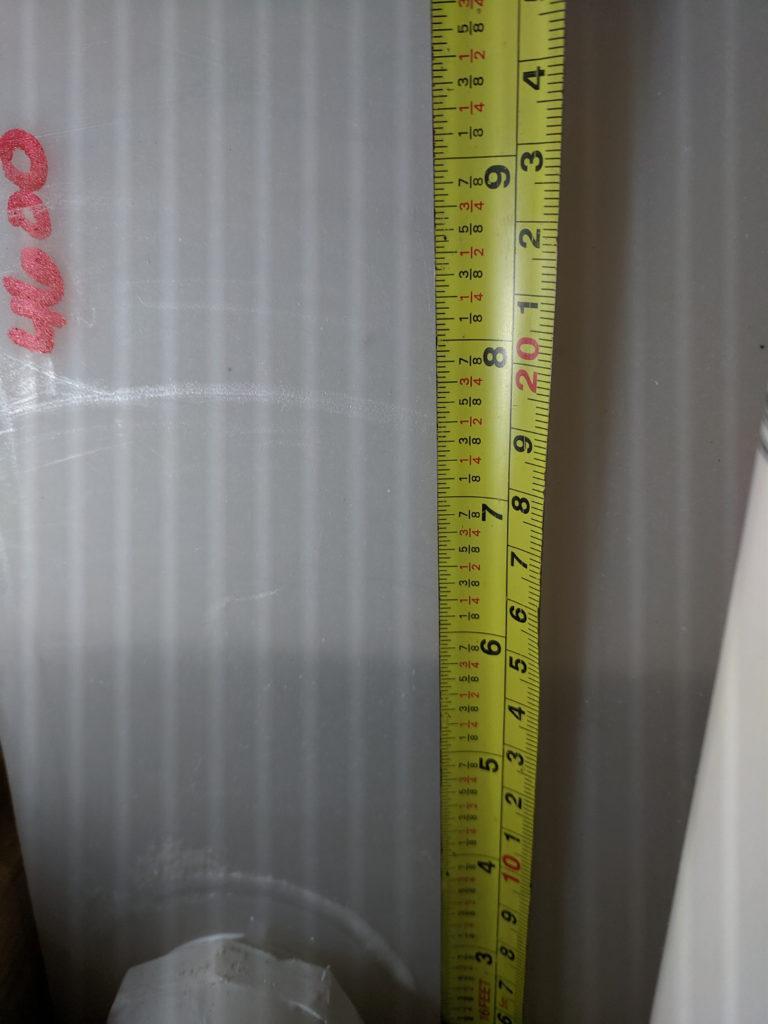
To test the accuracy of the data, I partially filled the water tank. Then, I manually measured the depth with a measuring tape. Next, I compared the measurement against the data. In conclusion, the data is trustworthy.
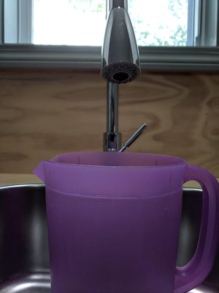
The Water Flow Sensor Test
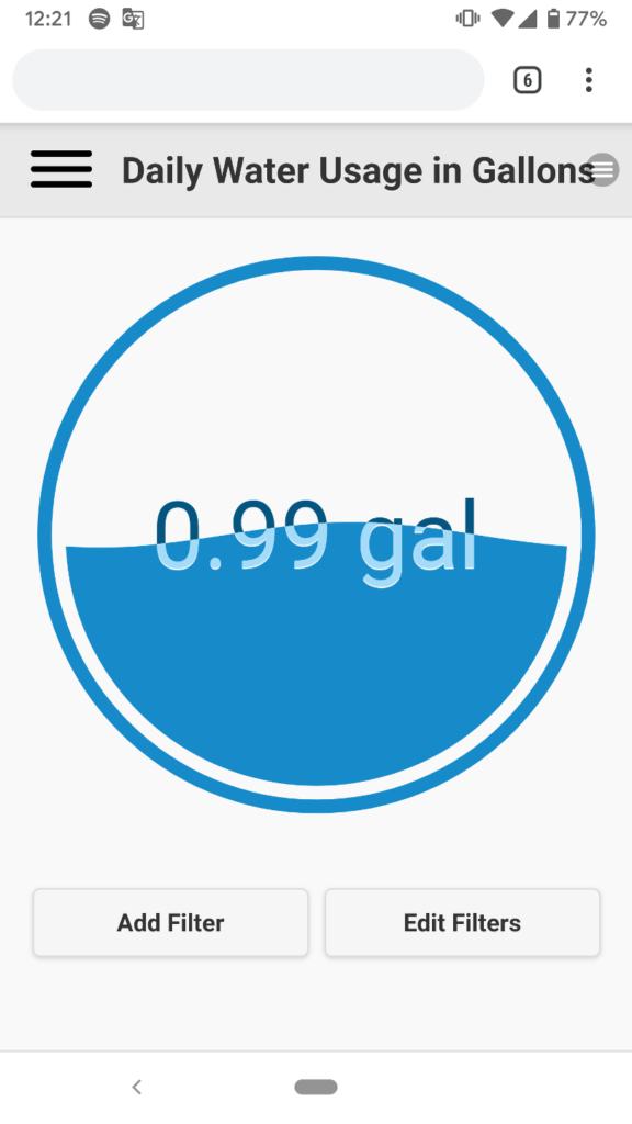
I filled a one gallon rubbermaid pitcher with water from the sink, and then compared the data results. Thankfully, the results show that the water flow sensor will track water usage reliably.
The Smart Plumbing System is a Go!
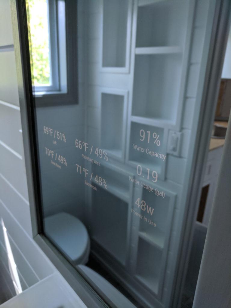
With the sensors in place and all tests complete, the sensors can now be put to good use. The MagicMirror shows the status of all sensors in the tiny house. For now, two more measurements are visible at all times. One shows how much water has been used in the last 24 hours, and the other shows the amount of water left in the water tank.
Conclusion
Plumbing is a critical system to any dwelling, and a tiny house is no exception. If this system were to fail or used improperly, it can cause problems. A smart plumbing system not only keeps an eye on the plumbing, it also collects data. Knowing water usage is important especially when one wants to conserve water and reduce water consumption. Sometimes the best habits are formed by simply being aware.
Regardless of the cool factor, there are more plans to make this system more interactive. In the meantime, I’ll be conscious of my water consumption, and sleep a bit easier knowing that I’ll be able to react to any leaks or possible freeze issues before they become bigger problems.